About Icons
CABINEX SeriesCABINEX-EWT
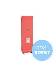
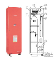
COX-50EWT
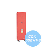
COX-50EWT-S
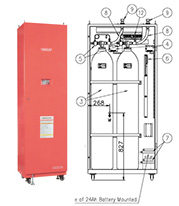
COX-100EWT
COX-100EWT-W
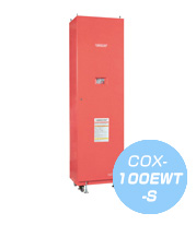
COX-100EWT-S
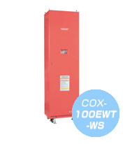
COX-100EWT-WS
Features
Automatic Fire Extinguishing System (CO2) for Semiconductor and Flat Panel Display Manufacturing
The CABINEX-EWT is an FM-approved product. Enhanced safety is guaranteed with this system that meets the global safety requirements of the semiconductor and flat panel display manufacturing industries.
- Compact and slim system configuration
- The dimensions of the extinguishing system are approximately 25% more compact than previous models.
- Control panel upgraded with flat panel display
- The standard control panel includes addressable points and history functions. On the flat panel display, you can now easily check which detector was activated at the time a fire or a fault was detected.
- CO2 for clean efficient extinguishing
- The CABINEX-EWT extinguishes fires thoroughly by releasing the CO2 extinguishing agent in amounts that meet FM requirements. The CO2 extinguishing agent is non-conductive and clean. Once released, it does not generate toxic substances that arise from thermal decomposition, and therefore does not adversely affect manufacturing equipment in clean rooms.
- Speedy and flexible after-sales service
- Fire extinguishing systems are not systems that operate on a daily basis, but they must work reliably in the event of a fire. Hatsuta, with its worldwide service network, provides necessary maintenance and speedy after-sales service.
- High quality, high performance
- CABINEX-EWT is manufactured in an ISO9001-certified factory based on a design that conforms to global standards, boasting world-class quality and performance.
- Optimal Fire Detector
- [Heat Detector] • THIS-10
[Triple Wavelength IR Flame Detector] • SX-7000
Specifications
| Product name | CABINEX-EWT | ||
|---|---|---|---|
| Model |
COX-50EWT |
COX-100EWT |
COX-100EWT-W |
| Approval | FM Approved | ||
| Extinguishing Agent | Carbon dioxide (CO2) | ||
| Extinguishing Agent Weight | 22.7 kg (50 LB) |
45.4 kg (100 LB) |
45.4 kg (100 LB)×2 |
| External Dimensions (H×W×D) mm |
1,530× 500×370 |
1,980× 550×400 |
1,980× 850×400 |
| Coating Color | Red | ||
| Total Weight | Approx. 170 kg |
Approx. 270 kg |
Approx. 400 kg |
| Operating Temperature Range | 0°C to 40°C | ||
| Power Input Range | AC100–120/187–240 V, 50/60 Hz | ||
| Power Consumption | 105 W Max. | ||
| Control Circuit Voltage | DC24V | ||
INPUT/OUTPUT
| Battery Input | 12 V DC battery x 2 | ||
|---|---|---|---|
| SI Module Input | 1 line | ||
| Manual Stations Input | 1 line | ||
| Discharge Module Input | 1 line | ||
| Relay Module Input | 1 line | ||
| Solenoid Actuator Output | DC24 V/1.0 A Max. | ||
| Horn & Strobe Output | DC24 V/0.5 A Max. | ||
| Output Voltage | DC24 V/1.5 A Max. | ||
| Fire Annunciating Relay | DPDT Contact (Form C contact x2) Rating: 60 W/125 VA, Voltage: AC250 V/DC200 V Max., Current: 1 A Max. |
||
| Pre-Discharge Relay | DPDT Contact (Form C contact x2) Rating: 60 W/125 VA, Voltage: AC250 V/DC200 V Max., Current: 1 A Max. |
||
| Fault Annunciating Relay | DPDT contact (Form C contact x2) Rating: 60 W/125 VA, Voltage: AC250 V/DC200 V Max., Current: 1 A Max. |
||
FUNCTION
| Discharge Delay Timer | Selectable between 0, 5, 10, 20, 30, 60 seconds |
||
|---|---|---|---|
| Number of Zones | 2 (AND/OR Selectable) | ||
| Detector Address | Max. 32 points | ||
| History Record | Max. 100 events (of which alarms: 50 events) |
||
| Alarm Stop | Push “Alarm Stop” switch to silence | ||
| Alarm Buzzer | Fire: continuous sound; Fault: intermittent sound |
||
| Manual Discharge | Push “Discharge” button to release extinguishing agent | ||
LED/SW
| Power LED | Green (Off when power down) | ||
|---|---|---|---|
| Pre-Discharge LED | Red (Flashes when in discharge pending. Off when discharge) | ||
| Discharge LED | Red (On when discharge activates) | ||
| Zone 1 Fire LED | Red (Flashes at Zone 1 alarm signal input) | ||
| Zone 2 Fire LED | Red (Flashes at Zone 2 alarm signal input) | ||
| Manual Discharge LED | Red (Flashes when manual release activates) | ||
| Fault LED | Yellow (Flashes in case of fault) | ||
| Discharge Disabled LED | Yellow (Flashes when discharge disabled activates) | ||
| Alarm Stopped LED | Yellow (Flashes when alarm is silenced) | ||
| Discharge Button | Red push button (display panel) | ||
| Power Switch | White toggle switch | ||
| Switch 1 | White push button (for address checking) | ||
| Switch 2 | White push button (for address checking) | ||
| Switch 3 | White push button (for address checking) | ||
| Alarm Stop Switch | White push button | ||
For more information, please contact our sales representatives.